When I first started running our custom turned parts shop six years ago, I’ll admit I treated cutting speed like a checkbox on a job sheet. A customer would specify a material—say, 6061 aluminum or 304 stainless steel—and I’d reach for the speed chart, punch in a number, and pull the lever. It wasn’t until a client waited three extra weeks for a batch of medical device fittings that warped during turning that I realized cutting speed wasn’t just a number—it was the heartbeat of every custom turned part leaving our shop. That single lesson turned me into the guy standing next to our lathes at 7 a.m., adjusting parameters mid-run, asking our operators “What’s the speed feeling right now?” instead of just what the manual says. Today, I want to pull back the curtain on how cutting speed shapes every layer of custom turned parts production, from surface finish to part longevity, and how that directly impacts the guys and gals who depend on our work. Custom Turned Parts
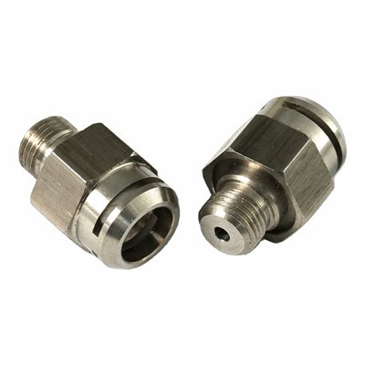
Let’s start with the obvious: cutting speed is how fast the edge of a turning tool moves across the surface of your workpiece, measured in surface feet per minute (SFM) or meters per minute (m/min). For our team, it’s never a one-size-fits-all number. Last month, we had two jobs on the same day: a run of 200 small 17-4 PH stainless steel bushings for a aerospace valve manufacturer, and a prototype of a brass connector for a brewery’s keg system. For the stainless bushings, we ran at 150 SFM—slower than the industry average for stainless, because I’d learned from past mistakes that cranking it higher caused built-up edge (BUE), that ugly layer of workpiece material that welds to the tool tip and gouges the part’s surface. For the brass connector prototype, we ran at 400 SFM, a speed that let us get a mirror-like finish without any chatter marks. The difference wasn’t random: it came from years of testing on our three Haas ST-10 lathes, and from talking to our CNC operator, Rico, who’s turned more custom parts than I can count. That’s the thing about custom turned parts—every job has its own rules, and cutting speed is the first rule.
One of the most immediate effects of cutting speed is surface finish, and for 90% of our clients, that’s non-negotiable. Let’s break this down. If you run too slow, you’re not just spending extra time on the job—you’re making the tool rub against the workpiece instead of cutting it. That friction generates a ton of heat, and heat doesn’t play nice with soft materials like aluminum or brass. We once had a client in the automotive industry send back a batch of aluminum spacers that had a dull, grainy surface, and when we tested it, we saw we’d run at 100 SFM, 50 SFM lower than we should have. The rubbing action pulled tiny aluminum grains out of the surface, leaving it rough enough that the client couldn’t get a proper seal on their fuel lines. Cranking the speed to 150 SFM? We got a smooth surface that passed their pressure test on the first re-run. But go too fast, and you get the opposite problem: chatter. Chatter is that high-pitched vibration that makes the tool jump across the workpiece, leaving wavy lines you can see with the naked eye. For a medical device part, that’s a dealbreaker—those wavy lines can harbor bacteria, so our clients in orthopedics and diagnostic equipment won’t accept a surface with more than 0.8 Ra, and chatter is the number one cause of higher Ra values. Last quarter, we worked with a startup making custom titanium implants, and their first prototype had chatter marks. We adjusted the cutting speed from 80 SFM to 95 SFM, slowed down the feed rate just a touch, and the Ra dropped to 0.72—good enough for their FDA submission. It’s a delicate balance, and that’s what makes custom turning different from mass-produced parts: we tweak that balance for every single job.
Next up is tool life, and this is where cutting speed hits our bottom line and our clients’ wallets hard. A cheap tool costs $10, but if it only lasts 10 parts, that’s $1 per part—add that up over a 1,000-part run, and that’s $1,000 in tooling costs alone. Run at the right speed, and that same tool might last 50 parts, bringing the cost down to $0.20 per part. Let’s use our recent 304 stainless steel shaft job as an example. We tried running at 180 SFM (the top of the manufacturer’s suggested range) and our carbide insert burned out after 75 parts. The insert cost $12, so that’s $0.16 per part in tooling. We dropped the speed to 130 SFM, and the same insert lasted 220 parts—tooling cost dropped to $0.05 per part, a 68% savings. But wait, if slower is better for tool life, why not run as slow as possible? Because that’s where the cycle time comes in, and time is money for everyone. A job that takes an extra hour to run means our clients wait longer, and our overhead (electricity, labor, machine wear) goes up. That’s why we test three speeds for every new material: low, medium, and high, and pick the sweet spot where tool life is long, cycle time is short, and the part meets specs. We’ve even turned that into a selling point: when a client asks for a rush job, we don’t just jack up the speed—we adjust it to get the part out in half the time without burning out tools or ruining finish.
One area where cutting speed is especially critical is precision, and custom turned parts are all about precision. For jobs like injection molding cores and pins, a 0.001-inch error can mean the difference between a perfectly molded part and a scrapped mold that costs thousands. Let’s talk about thermal expansion, which is the hidden enemy here. When you run a cutting tool at high speed, the heat generated softens both the tool tip and the workpiece. For small parts, that softening makes the workpiece expand—so you cut it to 0.500 inches when it’s warm, and by the time it cools down, it’s 0.498 inches, too small for the client’s assembly. We ran into this last year with a batch of 500 4mm diameter titanium pins for a robotics company. The client needed a tolerance of ±0.002mm, and our first run at 120 SFM resulted in parts that were 0.005mm too small after cooling. We dropped the speed to 90 SFM, which cut the heat enough that the expansion was negligible, and every single pin was within tolerance. It’s not just about heat, either—chatter from too high a speed can throw off tool alignment, making the part’s diameter inconsistent along its length. For a 12-inch aluminum tube for a hydraulic cylinder, that inconsistency means the seal leaks, so the entire part is useless. We’ve learned to use a laser micrometer mid-run on critical jobs, checking diameter every 50 parts to make sure the speed isn’t causing any drift.
Now, let’s get real about what this means for our clients, because at the end of the day, they don’t care about SFM charts—they care about getting parts that work, on time, without breaking the bank. A few months ago, we had a small medical device client come to us after a bad experience with a cheap overseas supplier. They were getting custom turned fittings that had rough surfaces, consistent diameter errors, and tool marks that made them fail inspection 30% of the time. When we took a look at the supplier’s process, we saw they were running every part at the same high speed, regardless of material or size—cutting corners on tool changes and time to keep costs low. We offered to run the same job, adjusted the cutting speed for each material grade, tested for thermal expansion, and used a polished tool insert to get the surface finish. The first batch we sent them had a 0% failure rate, and they’ve been a repeat client ever since. That’s the real impact: cutting speed isn’t just a technical detail—it’s the difference between a part that works and one that costs a client their reputation.
I also want to talk about how we adjust cutting speed for prototype jobs, because that’s a big part of our business. Producers often come to us with a new design, a small run of 10 to 50 parts, and they need parts that are not just functional, but accurate enough for testing. For prototypes, we usually run at a slightly lower speed than production runs, because prototypes are often made from different material batches or have unusual geometries that can cause chatter at higher speeds. We also test multiple speeds on the prototype to see which gives the best balance of finish and tool life, so when we move to production, we already have a optimized parameter. Last year, a startup making electric scooter parts came to us with a prototype of a custom aluminum crank arm. The first prototype we ran at 200 SFM had a surface finish that was great, but a slight bend due to chatter. We dropped the speed to 150 SFM, and not only did the bend go away, the tool life doubled, making the production run of 500 parts cheaper than the original prototype estimate. That’s the kind of flexibility custom turned parts offer, and cutting speed is at the center of that.
Of course, no discussion of cutting speed is complete without talking about safety, something we never cut corners on. High cutting speeds generate a lot of chips, which can fly off at hundreds of feet per minute if not controlled. If the speed is too high, chips can become long, stringy, and hard to contain, creating a safety hazard for our operators. We’ve had operators come to me with safety concerns about long chips wrapping around the workpiece, so we adjust the cutting speed (and the feed rate) to make chips break into small, manageable pieces that are easy to remove. It’s another example of how every part of the process is connected—cutting speed impacts safety, which impacts our ability to deliver consistent parts on time.
After six years in this business, I’ve seen too many shops treat cutting speed like a generic number, but for custom turned parts, it’s personal. Every job is different, every material reacts differently, every client has unique specs, and that means every cutting speed needs to be tested, adjusted, and tuned to that specific job. It’s not just about following a chart—it’s about listening to our operators, learning from every bad batch, and working with our clients to find the sweet spot that works for them.
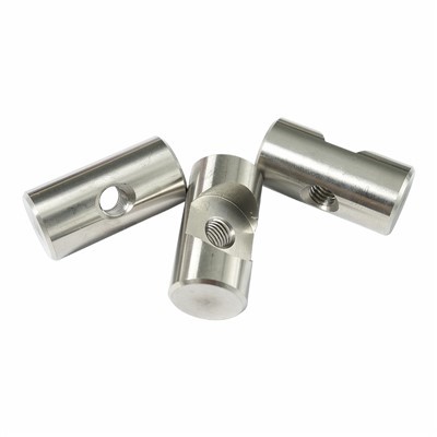
If you’re working on a project that needs custom turned parts—whether it’s a medical device, aerospace component, automotive part, or a prototype for a new product—you don’t want to leave the details of cutting speed to chance. We’ve spent years perfecting that balance, and we’d love to sit down with you to talk about your project, walk through our process, and make sure every part we deliver is exactly what you need. Get in touch with our team to discuss your custom turned parts requirements today.
CNC Turning References
- ASTMB211-19, Standard Specification for Aluminum and Aluminum-Alloy Bar, Rod, and Wire
- DeGarmo, E. P., Black, J. T., & Kohser, R. A. (2020). Materials and Processes in Manufacturing (13th ed.). Wiley.
- Smith, G. T. (2017). Cutting Technology: Principles and Practice of Machining. Industrial Press.
- ISO3685:2019, Tool Life Testing for Single-Point Turning Tools
Huizhou Quanyi Precision Hardware Products Co., Ltd.
Address: Building A10, 7th Floor, Zhongchuangyingke 5G Industrial Park, Zhonghan Industrial Park, Tonghu Town, Huizhou City
E-mail: info@qycncturning.com
WebSite: https://www.qycncturning.com/
